Share this
Elite Piping Manufacture is a powerful flange orifice plate manufacturer. Flange orifice plates are the main business direction of Elite Piping Manufacture . We have always regarded meeting customer requirements as the core of our business operations. We strictly control quality and strive to improve efficiency. Our company persists and strives to provide demand groups with flange orifice plates that meet market needs.
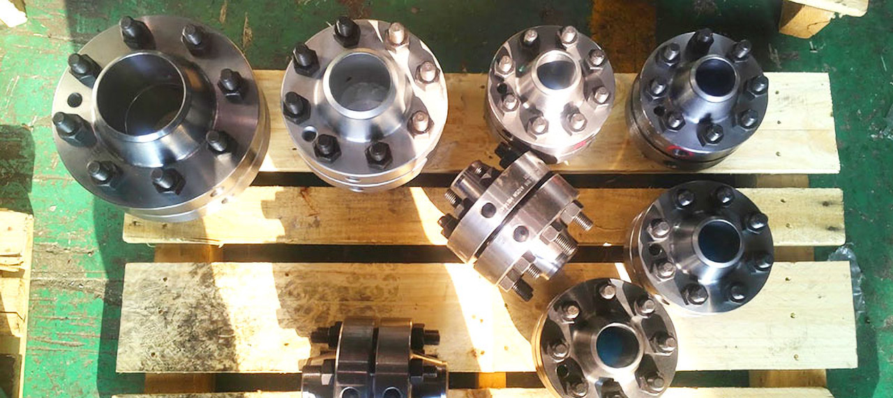
The plate orifice flange is a component of the orifice plate flowmeter, which appears in pairs. The plate orifice flange uses the pressure difference on both sides of the flow orifice plate to measure, and then calculates the flow rate of the material based on the formula. The orifice flowmeter consists of a flow orifice plate, an orifice plate flange, a pressure guiding tube, and a differential pressure flow transmitter.
Orifice plate flanges are usually raised faces or ring connection faces, and are generally the same as standard neck butt welding flanges and neck flat welding flanges, except for more machining. The picture below shows an orifice plate flange group, with an orifice plate in the middle and lifting bolts on the flange. The function of the lifting bolt is to help the flange separate so that the orifice plate and flange gasket can be inspected or replaced.
The orifice flow meter manufacturing and installation technology is most commonly used in natural gas measurement. It consists of a throttling device, a pressure guide tube, a differential pressure meter, a pressure gauge and a thermometer. Under normal circumstances, its measurement accuracy can meet the requirements of national standards and Ministry of Petroleum standards. However, in actual work, due to the fact that the design, manufacture, installation and use of the throttling device do not meet the standard requirements, improper parameter selection, user load changes, inaccurate manual value selection and other reasons, all affect the accuracy of flow measurement to varying degrees. The throttling device, also called a differential pressure flow meter, is composed of a primary detection component (throttle component) and a secondary device (differential pressure transmitter and flow indicator) and is widely used in gases. Flow measurement of steam and liquids. It has simple structure, convenient maintenance and stable performance. Therefore, finding out the causes and solutions of orifice flowmeter measurement errors is an important task related to accurate measurement.
The application of flange orifice plate
The orifice plate flowmeter is a high range differential pressure flow device composed of a standard orifice plate and a multi-parameter differential pressure transmitter (or differential pressure transmitter, temperature transmitter and pressure transmitter). It can measure gas, Steam, liquid and pilot flow are widely used in process control and measurement in petroleum, chemical industry, metallurgy, electric power, heating, water supply and other fields.
Flange orifice plate manufacturing and installation
When using an orifice plate flowmeter, the technical requirements for orifice plate processing are very strict and must comply with the provisions of national standards or ministerial standards. Otherwise, errors will be caused in the natural gas flow measurement results.
(1) Orifice plate eccentricity: Experiments show that the measurement error caused by orifice plate eccentricity is generally within 2%. The higher the aperture ratio β value, the greater the impact of eccentricity. Therefore, orifice plates with high β values should be avoided.
(2) Orifice plate bending: Due to improper installation or maintenance, the orifice plate is bent or deformed, resulting in large flow measurement errors. The test results were carried out on the orifice plate where the flange takes pressure. The maximum error caused by the bending of the orifice plate is about 3.5%.
(3) Protrusions in the throttling device: Gaskets, welds, etc. that protrude into the pipe in the throttling device will also cause certain errors in flow measurement. The size of the error depends on the position of the protrusions, the distance between the orifice plate and the protrusions, and Highlighting height. Tests have shown that when β = 0.7 and the protruding object is located at 2 times the pipe diameter upstream of the orifice plate, the error will be the largest; if the protruding object is located at the upstream orifice plate, the error will be 16% to 50%. Downstream, the impact on measurement accuracy is smaller.
Ways to improve measurement accuracy
(1) Pipeline requirements: National standards have strict technical requirements for metering pipe length, straight pipe, roundness and internal surface roughness. When the minimum length of the metering tube cannot meet the standard requirements, it will bring deviation to the flow measurement results. The size is related to the aperture ratio β and Reynolds number. Therefore, a rectifier must be installed on the straight pipe in front of the orifice plate to ensure measurement accuracy.
(2) Installation requirements: The inlet end face of the orifice plate must be perpendicular to the axis of the pipeline, and its deviation cannot exceed 1 degree. When installing the orifice plate, pay attention to the direction of the pipe. Reverse installation is strictly prohibited and must comply with the standard requirements for non-axial tolerance. The thickness of the sealing gasket between the flange, orifice plate and pressure sensing device shall not be greater than 0.03D. The installation of the gasket shall not protrude into the straight pipe section or the inner cavity of the pressure tapping device, and shall not block the pressure tapping port or cause a change in the pressure tapping position. In a newly built station, the orifice plate must be installed on the throttling device after the pipeline has been purged and run for several days to prevent the orifice plate from being damaged or contaminated by liquid and solid impurities in the gas.
Regulations on conditions for use of flange orifice plates
(1) The measured medium should fill the entire pipeline section and flow continuously.
(2) The flow stream (flow state) in the pipeline should be stable.
(3) The measured medium should not undergo phase change when passing through the orifice plate (for example: the liquid should not evaporate, and the gas dissolved in the liquid should not be released), and should exist in a single phase. Media with complex components can only be used if their properties are similar to media with a single component.
(4) Condensate or dust that is precipitated when measuring gas (steam) flow, or gas or sediment that is precipitated when measuring liquid flow, must not accumulate near the orifice plate in the pipeline, nor in the connecting pipe.
(5) When measuring the flow rate of media that can cause clogging of the orifice plate, the core must be cleaned regularly.
(6) On the inner surface of the pipe 2D away from the front and rear end faces of the orifice plate, there are no protrusions or roughness and unevenness visible to the naked eye. For standard nozzles. Standard venturi nozzles and standard venturi tubes, these conditions apply.
Precautions for orifice plate flange
Orifice plate flanges are easy to install and low in cost because of their simple manufacturing process. Therefore, it is widely used, but special attention should be paid when using it, especially when it is used to measure corrosive media and media containing dust with flow. Always observe whether the measurement results are accurate to prevent corrosion and blockage of the pressure port. If the measurement error is too large, or the measurement cannot be performed at all, the orifice plate should be cleaned during annual overhaul. If serious corrosion is found, a new orifice plate should be replaced immediately.
If you are interested in our flange orifice plates, you are welcome to contact us.

